
Energy-Saving Technologies in PET Preform Injection Molding
In high-speed rigid packaging production, energy consumption represents one of the single largest operating costs alongside raw resin procurement. Producing Polyethylene Terephthalate (PET) preforms requires converting electrical power into thermal energy for resin melting, mechanical torque for plasticization, hydraulic/electric clamping force, and refrigeration energy for heat extraction. Key metrics on the plant floor are measured in specific energy consumption—typically expressed as kilowatt-hours per kilogram of processed PET (kWh/kg).
While machine drive choices (such as switching from hydraulic to servo-electric systems) play an important role, the primary driver of overall line energy efficiency lies within the engineering architecture of the PET preform mold itself. As a premier global PET preform mold manufacturer and solution specialist, Apexmolds conducts deep-dive analyses into how advanced mold design reduces energy demand across the entire injection molding cycle.
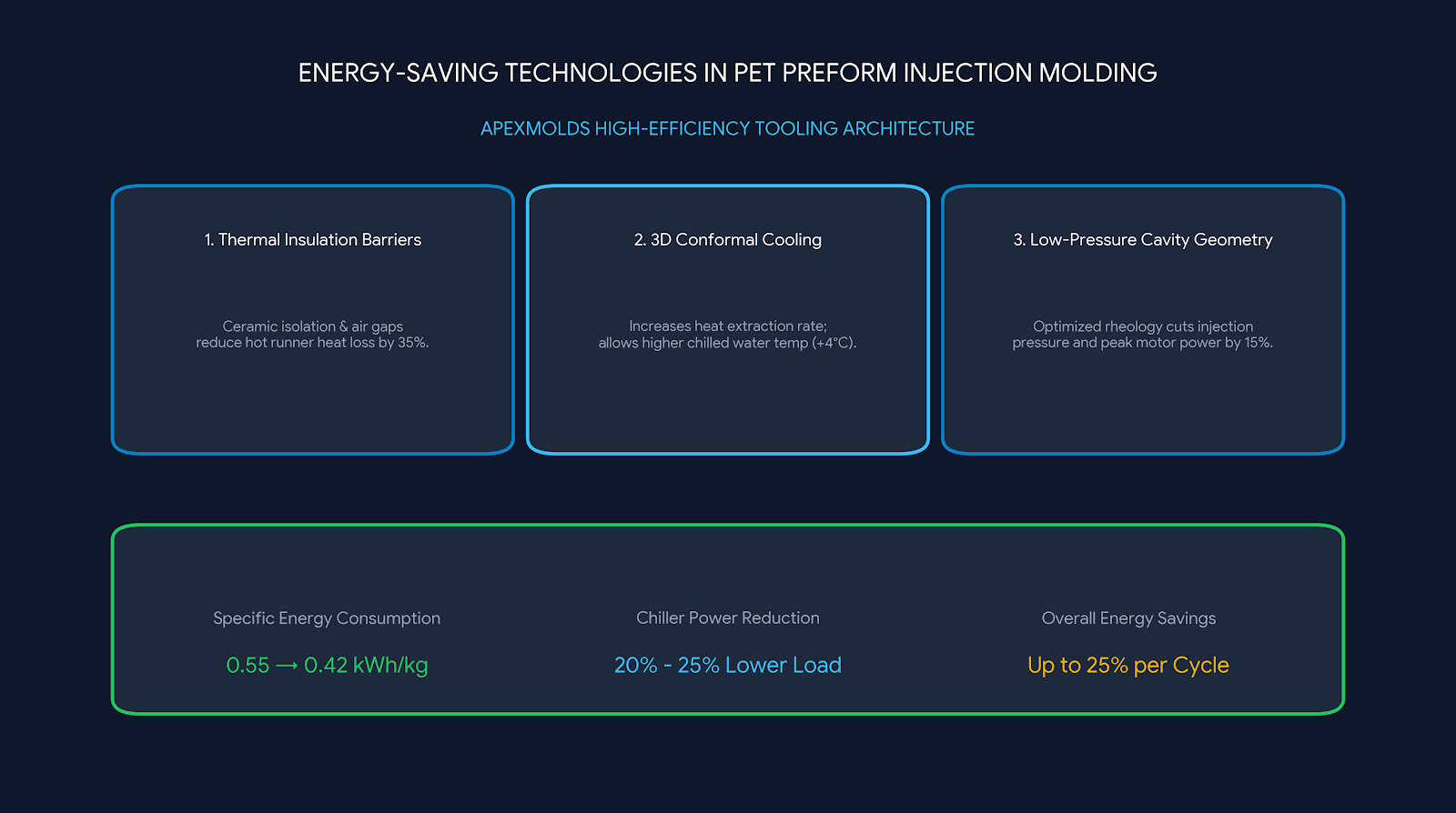
Key Technical Insight: Over 60% of total electrical power consumed in PET preform manufacturing is split between barrel/hot runner heating and chiller pump work for cooling. By engineering hyper-balanced hot runners, reduced injection pressure geometries, and optimized 3D conformal cooling circuits, Apexmolds tooling directly reduces line energy consumption by up to 18% to 25% per kilogram of finished preforms.
1. The Thermodynamics of PET Preform Molding: Where Energy Goes
Understanding energy efficiency requires mapping heat input and heat removal across the processing envelope. The thermal journey of PET resin follows strict thermodynamic laws:
- Thermal Input (Heating Phase): Virgin or rPET granules must be heated from ambient temperature up to 270°C–290°C. This requires approximately 0.25–0.30 kWh/kg of thermal energy supplied via screw shear friction and barrel band heaters, plus dedicated hot runner nozzle heating.
- Hydraulic & Mechanical Energy (Injection & Clamping): High injection pressures (often exceeding 120–160 bar melt pressure) and clamp tonnage holding force require substantial motor power. High melt flow resistance directly increases hydraulic and servo motor load.
- Thermal Extraction (Chilling Phase): The heat introduced during plasticization must be extracted by circulating chilled water (typically at 8°C–12°C). Chiller compressors and water circulating pumps draw significant continuous electrical loads.
2. Tooling Innovations: How Apexmolds Molds Drive Energy Savings
A. Optimized Hot Runner Thermal Insulation & Zoning
Uninsulated or poorly balanced hot runner manifolds radiate massive amounts of heat into the mold plates, forcing the mold cooling system to fight against heat bleeding from the hot runner manifold. Apexmolds incorporates multi-layer ceramic thermal insulation barriers and air gaps between the hot runner manifold and the mold frame plates. This reduces parasitic thermal loss by up to 35%, conserving heating electricity while dramatically reducing the cooling load on the chiller system.
B. Low-Pressure Cavity Geometry & Gate Design
Injection pressure is directly proportional to hydraulic or electric drive power ($P = p \cdot Q$). By utilizing Mold Flow Analysis (MFA) to optimize wall transitions, core gate radiuses, and valve gate pin profiles, Apexmolds reduces melt flow resistance. Lower injection pressure requirements allow processors to run on lower clamp tonnage machines or reduce peak servo motor power demands by 12% to 15%.
| Energy Sub-System | Standard Tooling Design | Apexmolds Energy-Saving Tooling Platform | Direct Energy Impact |
|---|---|---|---|
| Hot Runner Heating | Continuous full-power heating with high thermal dissipation into plates | Micro-zone PID control with ceramic insulation barriers & low-mass nozzles | 15% – 20% reduction in hot runner kWh draw |
| Chiller Water Load | Straight drilled lines; slow cooling requiring colder water (6°C) | 3D conformal cooling & BeCu inserts; higher water temp (10°C–12°C) permitted | 20% – 25% lower chiller compressor energy consumption |
| Plasticization Load | High melt resistance due to abrupt cavity transitions | Rheologically optimized wall tapers & valve gate flow channels | 10% – 14% lower injection motor peak power draw |
| Weight / Material Usage | Standard thick-walled neck finish & body profiles | Lightweight neck finish (PCO 1881 / 29/25) & thin-wall engineering | 8% – 12% lower overall resin processing mass per shot |
C. High-Efficiency Conformal Cooling & Higher Chilled Water Setpoints
Conventional preform molds rely on deep-drilled straight water channels that often require freezing water temperatures (around 6°C) to achieve fast cycle times, causing condensation (sweating) on mold surfaces and demanding high chiller compressor effort. Apexmolds 3D conformal cooling channels and Beryllium-Copper (BeCu) core tips remove heat so efficiently that plants can raise their chiller water supply temperature from 6°C to 10°C–12°C without increasing cycle times. Raising chiller water temperature by just 1°C improves compressor COP (Coefficient of Performance), yielding a 3% to 4% direct energy savings on the chiller plant.
D. Lightweight Preform Design Engineering
The greenest energy is the energy not used. Apexmolds partners with customers to redesign preforms for optimal strength-to-weight ratios. By lightweighting neck finishes (e.g., transitioning from PCO 1810 to PCO 1881 or 29/25) and optimizing body wall distribution, a 1g to 2g reduction per preform equates to hundreds of metric tons less resin plasticized annually—yielding exponential energy savings across plasticizing, injection, and blow molding stages.
3. Overall Plant Impact: Lowering kWh per Kilogram
When evaluated across a full production year operating a 48-cavity or 72-cavity preform molding line, the cumulative energy savings achieved through Apexmolds engineered tooling deliver significant financial returns:
- Specific Energy Consumption Reduction: Average line energy drops from ~0.55 kWh/kg down to 0.42 – 0.45 kWh/kg.
- Reduced Carbon Footprint: Lower kWh/kg metrics directly translate to hundreds of metric tons of reduced CO₂ emissions annually per production line, helping packaging suppliers meet stringent ESG and sustainability mandates.
- Extended Auxiliary Equipment Life: Reduced thermal loads extend the operating life of chillers, mold dehumidifiers, and hot runner controllers.
4. Why Choose Apexmolds as Your Sustainable Tooling Partner?
At Apexmolds, energy efficiency is not an afterthought—it is a core engineering requirement integrated into every mold design. From certified Swiss S136 stainless steel construction to computational fluid dynamics (CFD) heat extraction modeling, our preform molds (ranging from 8 to 144 cavities) are tailored to deliver maximum output at the lowest energy cost per unit.
Whether you are upgrading an existing line or building a new high-speed sustainable preform production plant, Apexmolds provides complete technical consultation, flow analysis, and energy audit services to ensure your investment delivers maximum productivity and environmental efficiency.
Optimize Your Preform Plant's Energy Efficiency Today
Contact the Apexmolds technical team to run a mold flow thermal simulation or request a custom proposal for high-efficiency PET preform tooling.