
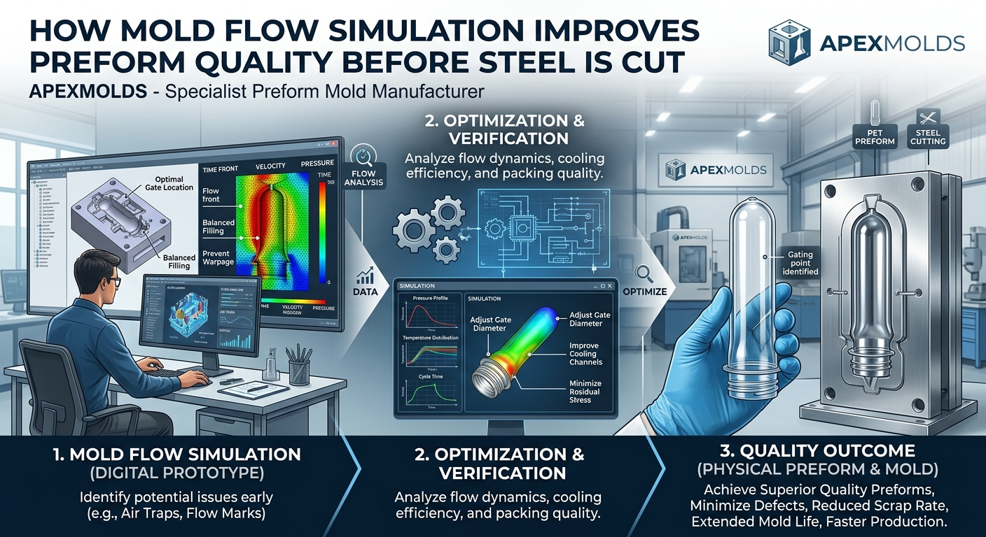
How Mold Flow Simulation Improves Preform Quality Before Steel Is Cut
In high-cavity PET preform manufacturing (ranging from 48 to 144 cavities), tool modification post-machining is exceptionally costly. Altering hardened stainless steel inserts (such as Swiss S136 at HRC 48–52) due to unforeseen wall thickness variation, gate crystallization, or filling imbalance leads to expensive project delays and compromised tool longevity. Modern preform engineering demands that defect identification and resolution take place entirely within the digital domain.
Utilizing Advanced Finite Element Analysis (FEA) and Computer-Aided Engineering (CAE) Mold Flow Simulation tools allows engineers to simulate melt rheology, thermal exchange, and structural pressure dynamics under production-level injection conditions. As a premier global PET preform mold manufacturer and turnkey solutions specialist, Apexmolds integrates full-scale Mold Flow Analysis into every project. Here is how virtual testing guarantees zero-defect preforms before CNC machines make their first cut.
The Engineering Advantage: Identifying melt imbalance, high shear stress, or core deflection in digital 3D models reduces tooling design revisions by 90%, protects tool life beyond 10 million cycles, and ensures initial T1 samples hit strict dimensional tolerances on shot one.
1. Critical Preform Deficiencies Prevented by Mold Flow Analysis
Injecting molten PET at temperatures between $270^\circ\text{C}$ and $300^\circ\text{C}$ under high injection pressures ($700 - 1000\text{ bar}$) creates extreme physical stress inside the cavity. Mold flow simulation precisely maps these factors to prevent physical defects:
- Core Shift and Wall Eccentricity: High injection pressure differential across the core rod causes micro-bending. A core shift of just $0.05\text{ mm}$ causes wall thickness variations, leading to uneven stretching during blow molding and bottle failure.
- Acetaldehyde (AA) & Thermal Degradation: Excessive shear rates inside hot runner nozzles or gate tips overheat the PET resin, causing high AA levels that taint water taste. Simulation maps shear rate distribution to keep melt stress within safe thresholds.
- Air Traps and Gate Haze: Insufficient cavity venting causes localized gas combustion (burn marks) or micro-voids near the gate. Simulation pinpoints exact air trap coordinates to optimize vent channel geometry.
2. Key Simulation Modules in Apexmolds Tooling Development
| Simulation Focus Area | Simulated Physical Variable | Apexmolds Optimization Action |
|---|---|---|
| Filling & Packing Balance | Melt front velocity, pressure drop, volumetric shrinkage | Adjusts hot runner nozzle diameters and runner balancing for equal multi-cavity fill. |
| Core Deflection Analysis | Fluid-Structure Interaction (FSI), radial pressure forces | Optimizes core pin taper design and lock mechanism to ensure concentricity ≤ 0.03mm. |
| Thermal & Cooling Optimization | Cooling channel fluid dynamics, heat dissipation rate | Designs conformal cooling circuits in core and cavity inserts to prevent gate haze. |
| Shear Rate & Stress Mapping | Viscous dissipation, shear stress at runner boundaries | Refines runner transition radii and valve tip geometry to minimize AA generation. |
3. Deep-Dive: Core Shift Prevention via Fluid-Structure Interaction (FSI)
The core pin of a PET preform mold is an elongated cantilever beam subjected to high radial hydraulic forces as molten resin fills the cavity. If the melt front does not advance with perfect rotational symmetry around the core, a lateral force differential shifts the core pin off-center.
Apexmolds utilizes Fluid-Structure Interaction (FSI) analysis to solve this challenge:
- Melt Front Mapping: The software calculates exact pressure distributions surrounding the core at $0.001\text{-second}$ intervals during the filling phase.
- Deflection Prediction: Structural FEA calculates the mechanical deflection vector of the core pin under asymmetric pressure loads.
- Gate & Taper Calibration: Engineers adjust the gate entrance angle, runner sizing, and neck-ring taper alignment geometry to balance radial forces, keeping core deflection strictly below $0.02\text{ mm}$.
4. Optimizing High-Cavity Hot Runner Rheology
In a 72- or 96-cavity preform mold, melt travelling to the central cavities experiences a different thermal and shear history compared to melt reaching corner cavities. Unbalanced flow leads to weight variations across preforms produced in the same shot.
Through simulation, Apexmolds engineers optimize manifold internal channel diameters, branch radii, and valve pin stroke profiles. This ensures that every cavity experiences identical pressure drops and thermal conditions, achieving weight tolerances within $\pm 0.1\text{ grams}$ across all cavities.
5. Apexmolds Engineering Workflow: From CAE Model to Machined Steel
Our systematic engineering methodology integrates digital simulation directly into our manufacturing pipeline:
- Step 1: 3D Geometry & Rheology Setup: Input resin-specific viscosity curves (including 100% rPET grade data) into the CAE system.
- Step 2: Iterative Simulation & Layout Refinement: Run filling, cooling, and core shift analyses to refine runner geometry and cooling line placement.
- Step 3: Precision CNC Tool Machining: Export optimized 3D CAD models directly to high-speed 5-axis CNC machining centers for steel fabrication.
- Step 4: T1 Verification: Validate physical T1 preform samples via optical CMM measurement to confirm compliance with CAE model predictions.
Validate Your Preform Tooling with Apexmolds CAE Expertise
Planning a high-cavity PET preform mold project or updating preform designs for lightweighting? Partner with Apexmolds to verify performance through advanced simulation before steel is cut.