
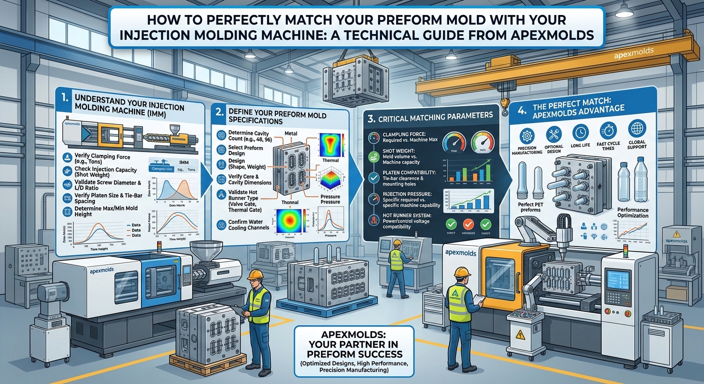
How to Perfectly Match Your Preform Mold with Your Injection Molding Machine
In PET container production, purchasing a high-precision preform mold and a top-tier injection molding machine does not automatically guarantee high efficiency, low scrap rates, or rapid cycle times. The true performance bottleneck often stems from a fundamental mismatch between the mold and the machine platform. A mismatch in clamping force, shot weight utilization, plasticizing throughput, or hydraulic/ejection interface can lead to severe parting line flash, thermal degradation of resin, excessive Acetaldehyde (AA) formation, or premature tooling destruction.
Achieving perfect mechanical, thermal, and hydraulic harmony between your mold and press requires rigorous engineering calculations rather than broad estimations. As a premier global PET preform mold manufacturer and engineering solutions provider, Apexmolds breaks down the essential criteria for achieving seamless mold-machine integration.
Key Takeaway: Tooling performance is constrained by machine capability. Perfect matching optimizes cycle time, preserves mold longevity, prevents thermal stress on PET resin, and ensures consistent preform wall tolerances across all cavities.
1. Precision Clamping Force (Tonnage) Calculation
Operating a mold on a machine with insufficient clamping force causes parting line flash, while excessive tonnage crushes mold parting faces, restricts cavity venting, and deforms core alignment pins over time.
To calculate the required clamping tonnage ($F_c$), determine the total projected area ($A_p$) of all cavities including the hot runner manifold drop surface, multiplied by the cavity injection pressure ($P_i$) and a safety factor ($K_s$):
$F_c = (A_p \times P_i \times K_s) / 1000$
- Projected Area ($A_p$): Sum of maximum cross-sectional area of preforms across all cavities in $\text{cm}^2$.
- Cavity Pressure ($P_i$): Typically ranges from 600 to 900 bar ($60 - 90 \text{ MPa}$) depending on preform wall thickness, flow length-to-thickness ratio ($L/T$), and PET intrinsic viscosity (IV).
- Safety Factor ($K_s$): A factor between 1.15 and 1.25 accounts for dynamic pressure spikes during holding phases.
2. Shot Size Utilization Window: The 30% to 70% Rule
Matching the total shot weight of the preform mold (preforms + hot runner melt volume per shot) to the injection unit’s maximum stroke capacity is vital for PET quality:
- Under-Utilization (<30% of Barrel Capacity): PET resin resides in the heated barrel for excessive cycles (high residence time). Thermal degradation occurs, resulting in elevated Acetaldehyde (AA) levels, yellowing, and loss of intrinsic viscosity (IV).
- Over-Utilization (>70% of Barrel Capacity): Plasticizing uniformity drops. Unmelted PET crystalline granules may enter the cavities, causing gate clogging, visual haze, and un-melt defects.
Apexmolds Gold Standard: Target total shot volume between 45% and 65% of the injection machine’s maximum stroke capacity for PET applications to maintain optimal residence times (<120 seconds).
3. Plasticizing Rate, Screw L/D Ratio, and Drive Power
PET requires specialized screw geometry to ensure uniform melting without excessive shear heating. Standard general-purpose screws are inadequate for PET preform molding.
| Parameter | Standard Plasticizing Specification | Apexmolds PET Engineering Standard | Operational Impact |
|---|---|---|---|
| Screw L/D Ratio | 20:1 – 22:1 (General Purpose) | 24:1 – 25:1 (Dedicated PET Profile) | Ensures complete melt homogeneity without thermal degradation |
| Compression Ratio | 2.5:1 – 3.0:1 | 1.8:1 – 2.2:1 (Low Shear) | Prevents mechanical shear stress & controls AA generation |
| Plasticizing Capacity | Matched to shot weight only | ≥ 1.3× required output rate (kg/hr) | Guarantees melt availability for high-speed cycle times (<8s) |
| Ejector Stroke & Force | Basic plate movement | Synchronized pneumatic + hydraulic ejection | Ensures damage-free take-out robot alignment |
4. Dimensional, Tie-Bar, and Physical Interface Clearance
Beyond process parameters, physical compatibility must be verified prior to installation:
- Tie-Bar Clearance: Verify that the mold base width and height clear the horizontal and vertical tie-bar distances. For high-cavity molds (e.g., 72 or 96 cavities), side-loading or top-loading clearance must account for robot end-of-arm tooling (EOAT).
- Mold Thickness Range (Min/Max Daylight): Ensure the closed mold height falls between the machine’s minimum and maximum platen shut height limits.
- Locating Ring & Sprue Bushing Radius: The machine nozzle radius must align with the mold sprue inlet radius (typically $R15\text{mm}$ or $R20\text{mm}$) to prevent melt leakage.
5. Integrated Auxiliary Systems: Hot Runner & Cooling Capabilities
A mold is an active thermodynamic system. Matching electrical and cooling utilities is just as important as mechanical fitment:
- Hot Runner Zone Controllers: Verify that the machine or external cabinet has sufficient independent PID temperature zones to drive all hot runner nozzle drops and manifold heaters.
- Chilled Water Flow & Pressure: Apexmolds preform molds require chilled water at 6°C–10°C with supply pressure of 4–6 bar to deliver high cooling rates. Ensure the plant chiller flow capacity matches the total manifold and cavity circuit requirements.
- Pneumatic Valve Gate Actuation Air: Clean, dry compressed air (6–8 bar) with dedicated accumulator tanks is required for precise pneumatic valve pin actuation without cycle delays.
6. How Apexmolds Engineering Simplifies System Integration
At Apexmolds, we eliminate trial-and-error by conducting comprehensive mold-machine compatibility simulations during the pre-engineering stage:
- Custom Interface Design: We adapt top-plate mounting hole patterns, locating ring dimensions, and knock-out rod positions to fit any major injection machine brand (Husky, Netstal, KraussMaffei, Engel, Haitian, Yizumi, etc.).
- Melt Flow & Thermal Balancing: 3D mold flow software models the exact melt pressure drop from machine nozzle to cavity tip, ensuring compatibility with your machine’s injection pressure limits.
- Turnkey Testing & Commissioning: Every Apexmolds tooling package undergoes dry-cycle tests and full-shot verification before shipment to ensure fast plug-and-play startup.
Get a Professional Mold-Machine Compatibility Audit
Planning to add new preform molds or optimize existing injection molding lines? Contact Apexmolds engineers today for a complete mold-machine matching analysis.